Recently, an article titled “Flexible hemline-shaped microfibers for liquid transport” was published in Nature Chemical Engineering. The authors of this paper studied a flexible half-shaped microfiber prepared using microfluidics for directional liquid transport.

Research Background
Directional liquid transport is important in both basic research and practical applications. Many efforts have been made to design microscale systems that exploit driving forces such as surface tension gradients, external driving forces, chemical gradients, and biomimetic anisotropic structures. Additionally some natural organisms have evolved surface structures to generate unbalanced forces and control directional fluid dynamics. Inspired by this, fiber materials with flexible shapes and asymmetric microstructures, achieved through techniques like electrospinning, three-dimensional (3D) printing, and microfluidic technologies, have garnered considerable attention in liquid transport studies. However, the transportation of different liquid types remains challenging due to variations in surface energy and surface effects influencing final transport behavior. Additionally, the intricacies of microfabrication necessitate platforms with directional transport capabilities across a spectrum of liquids and transport pathways, bridging the gap between fundamental liquid dynamics research and practical applications. In this study, microfluidics were utilized to fabricate flexible skirt-shaped fibers (Fig. 1). A vibrating flow configuration was developed within the microfluidic channel via piezoelectric control, transforming this configuration into solid skirt-shaped microfibers. These microfibers feature axially aligned cavities with sharp edges and annularly connected wedge angles. When placed on a common hydrophilic substrate without any specially designed surface structures, individual microfibers can create gaps with the substrate, allowing for directional liquid transport. Detailed observation of transport behavior by high-speed cameras revealed a process including unilateral pinning, continuous transport through the gap, and microcavity filling due to capillary rise. Intriguingly, closely adjacent fibers with the same or opposite angular orientations was found to produce a variety of liquid transport phenomena that were not limited by liquid type or surface wettability. Most notably, microfibers possess the inherent flexibility to transport fluids along 3D paths.Capitalizing on these advantages, the platform finds application in droplet manipulation, long-distance liquid transportation, and water-oil separation. These results demonstrate the versatility and generality of the proposed platform, with broad applications anticipated in open microfluidics, liquid transport along 3D paths, and energy and environmental engineering.
Graphical Guide
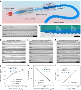
Figure 1: Using piezoelectric microfluidics to generate skirt-shaped spray templates. (a), Schematic illustration depicting the spinning process of skirt-shaped microfibers with programmable skirts via piezoelectrically induced fluid vibrations in microfluidic channels. (b), High-speed snapshots capturing a stable jet and a skirt-shaped jet (Qi = 4 ml/h, Qo = 14 ml/h, fp = 80 Hz, U = 7 V). (c), Computational fluid dynamics simulation showcasing the cross-sectional flow radial velocity profile and axial velocity profile (top) and streamline plot (bottom) during the formation of the skirt-shaped jet corresponding to (b). (d)-(f ), Real-time images exhibiting the skirt-shaped jet under various conditions: (d) different Qi /Qo ( Qi + Qo = 18 ml/h, fp = 80 Hz, U = 6 V); (e) piezoelectric driving frequency (Qi= 4 ml/h, Qo= 14 ml/h, U = 6 V); and (f) piezoelectric drive amplitude (Qi= 4 ml/h, Qo= 14 ml/h, f = 80 Hz). Function diagram of (g), epicting the relationship between dj and Qi/Qo. Function diagram of (h), illustrating the correlation between p and fp. Function diagram of (i), displaying the association between l and U.
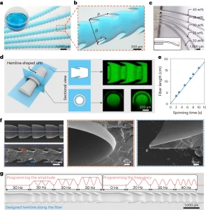 Figure 2: Characterization of Skirt-Shaped Microfibers (a), A batch of microfibers collected from a continuously spinning piezoelectric microfluidic platform. (b), Optical photograph showing that the obtained microfiber maintains the microstructure of the bottom edge, where D, l, and p represent the fiber diameter, bottom edge length and pitch respectively. (c). Fibers with different PEGDA concentrations exhibit different flexibility, denoted by wt% (weight percentage). The inset illustrates how flexible fibers deform; when one end is stabilized, the fiber bends under the influence of gravity. (d), Schematic and laser scanning confocal microscopy images exhibiting the compositional uniformity of microfibers and structural details of microcavities. (e). The relationship between fiber length and spinning time (Qi = 15 ml/h, Qo = 28 ml/h); the slope represents the spinning speed of microfibers. (f), Scanning electron microscopy image displaying the microstructure of skirt-shaped microfibers. Cutting along the axis (dashed line in upper left image) reveals a longitudinal section of the fiber (lower left image). Two magnified images depict details of the fiber corners (red dotted box area) and edges (blue dotted box area) with tip radius R (Qi = 30 ml/h, Qo = 56 ml/h, fp = 30 Hz). (g), Customized microfibers with skirts of different lengths and pitches obtained by programming input piezoelectric signals.
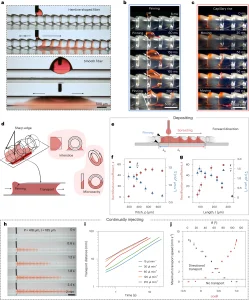 Figure 3: Directed Liquid Transport along Skirt-Shaped Microfibers attached to a Hydrophilic Substrate (a), Unidirectional liquid transport behavior along skirt-shaped fibers and bidirectional transport behavior along smooth fibers on hydrophilic substrates. (b), Time-lapse image showing the fixed effect of sharp edges at the top and bottom of the base. (c), Time-lapse image exhibiting continuous transmission behavior along an optical fiber attached to a glass slide. (d), Mechanisms responsible for directional liquid transport including pinning of sharp edges, capillary rise leading to microcavity filling, and continuous transport along the gap between the fiber and substrate. (e), Illustration depicting directional liquid transport when 2.5 μl droplets are deposited on the fiber. (f)-(g) , Rectification coefficient and average transmission velocity versus pitch (f) and microfiber base length (g). (h)-(j), Transport behavior of continuous injection in optimized morphology (p = 418 µm, l = 185 µm, injection flow rate 30 µl/min). (h), Typical time-lapse image of long-distance unidirectional liquid delivery under continuous injection. (i), Log-log plot of transmission distance as a function of time under different injection flow rates. (j), Plot of maximum transmission speed as a function of θ and cosθ, where θ is WCA.
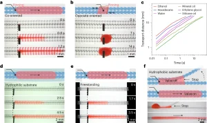 Figure 4: Continuous Liquid Transport on Two Contacting Microfibers (a)-(b), Water transport along contacting co- (a) and opposite-oriented (b) fibers placed on a hydrophobic substrate; (c), Log-log plot of transport distance versus time for different liquids by depositing 2.5 µl droplets; (d)-(e), Water transport along two co-oriented fibers placed on a hydrophilic substrate (d) without any contact on the substrate (e); (f), Control of transmission on/off by separating and bringing together two co-directional fibers placed on a hydrophobic substrate.
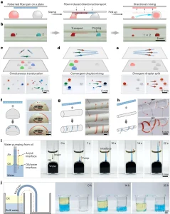 Figure 5: Application of Skirt-Shaped Fibers with Unidirectional Liquid Transport Capabilities (a)-(b), Schematic (a) and photograph (b) showing fiber-based “seals” for droplet manipulation. (c)-(e), Complex droplet manipulation using impressions with programmable fiber patterns, including simultaneous translocation of multiple droplets (c), convergent droplet mixing (d), and divergent droplet splitting (e); (f), Side view of a pair of co-directional fibers freely attached to the surface of a table tennis ball. By continuously depositing dyed water to one side, the water flows upward and climbs along the curve without retracting at the injection site. (g)-(h), Water on the surface of the pipette (g) and glass rod is transported along a spiral or pendant path (h); (i), Extraction of water from oil with the help of a pair of co-oriented fibers; (j), Large volume water transfer from a thick oil layer through a bundle of co-oriented skirt-shaped fibers.
Summarize
This paper reports a flexible half-shaped microfiber prepared using microfluidics for directional liquid transport. The microfibers are created by combining piezoelectrically induced vibrations of jets in microfluidic channels with rapid photopolymerization, resulting in ring-shaped connected microcavities with distinct edges and wedge-shaped corners. These unique structural features enable directional water transport due to unilateral fixation. Furthermore, precise control over microfluidic and piezoelectric parameters allows for tailored the structural characteristics of the microfibers, enabling control over transport capacity and speed. Demonstrated applications of these hem-shaped microfibers in smart droplet manipulation, multifunctional liquid delivery, and water/oil separation. In this study, PEGDA and water were used as two liquids, making it possible to directly solidify the liquid jet to obtain fibers. Taken together, the directional liquid transport properties of these hemifibers, as well as their ease of fabrication, versatility, and scalability, suggest a broad range of potential applications, including open microfluidics, water extraction, and real-life liquid transport, especially in environments with restricted materials or surfaces. Future research directions could involve integrating this approach with other technologies, such as 3D printing, to directly print fiber optic networks for water transport along predetermined paths. To expand the potential applications of this technology, stimulus-responsive functional materials can be incorporated into the internal phase to develop smart hem-shaped microfibers. Furthermore, by using this microfluidic platform, other types of UV-curable liquids could be explored to create fibers with diverse properties.
Reference:
Yang, C., Yu, Y., Shang, L. et al. Flexible hemline-shaped microfibers for liquid transport. Nat Chem Eng 1, 87–96 (2024). https://doi.org/10.1038/s44286-023-00001-5
Related Services:
One-Stop Microfluidic Solutions
Microfluidics-Based Analysis in Medical Science